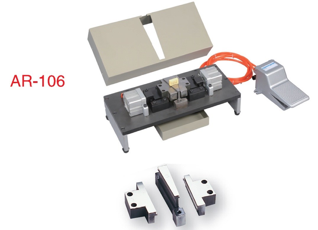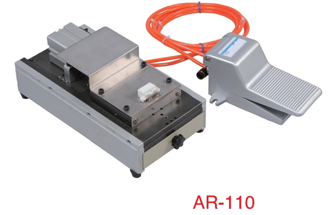
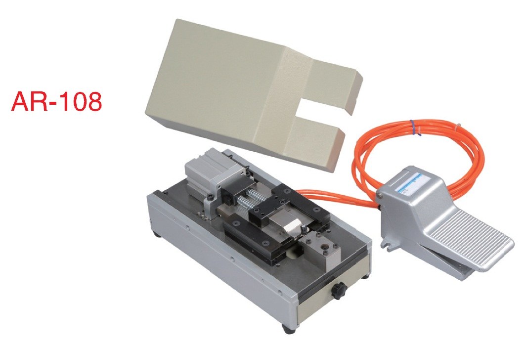
AR-108
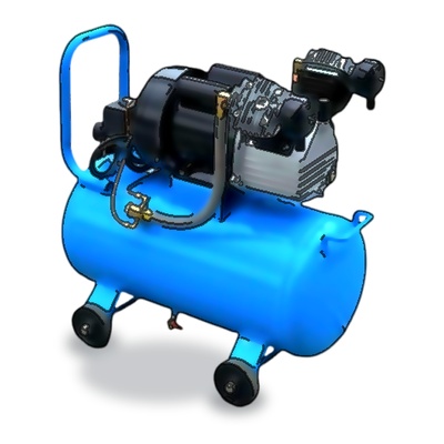
Air Drive Lead Forming Machine - Single Cylinder
氣動式零件引腳成型機-單氣缸
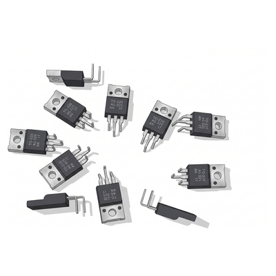
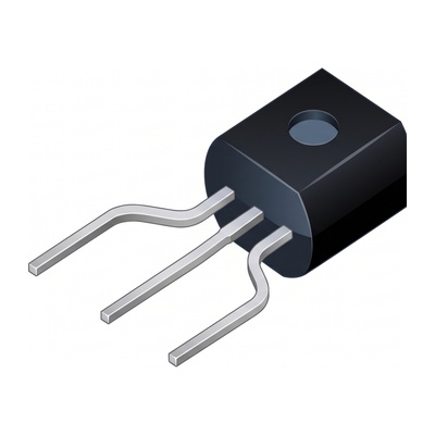
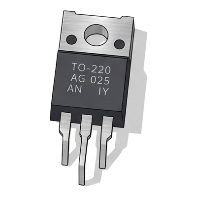
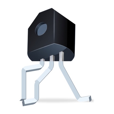
The AR-108 utilizes a single pneumatic cylinder for focused unidirectional stamping and lead trimming of transistors, power devices, capacitors, and resistors in one stroke. Its compact benchtop footprint and modular quick-change tooling allow tailored single-direction dual-stroke forming with high dimensional repeatability.

Machine Specifications & Performance
- Unidirectional Pneumatic Forming: Single air cylinder delivers focused, uniform stamping and forming force with high repeatability.
- Customizable Dual-Action Tooling: Supports single-direction dual-stroke forming cycles; engineering drawings are welcome for customized tooling solutions.
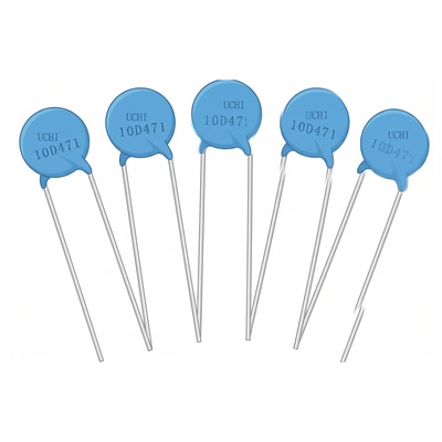
- Broad Component Versatility: Forms and trims various through-hole components including transistors, power devices, capacitors, resistors, and pre-formed leads.
- Single-Stroke Form & Trim: Precision shearing and forming completed in one stroke, ensuring fixed, repeatable lead dimensions.
- Compact Benchtop Architecture: Space-saving footprint with modular tooling design for swift, tool-free die changeovers.
- Dedicated Custom Tooling: Supplied standard with one custom-machined die set per customer specifications; additional die sets available for other component profiles.
Lead Forming & Geometric Parameter Specifications
Unit: mm / Custom tooling available★ Modes shown are common examples only. All tooling geometries (kinks, bends, pitch shifts) are fully customizable per drawings.
| Code | Parameter | Standard Value / Range | Engineering Notes |
|---|---|---|---|
| A | Component Body Height (A) [Example Mode 1] | 依元件規格 (Per Spec) | [Example Mode 1: 90° Bend] Component body height; tooling cavity designed accordingly |
| B | Component Body Thickness (B) [Example Mode 1] | 依元件規格 (Per Spec) | [Example Mode 1: 90° Bend] Component body thickness; forming nest precisely aligned to workpiece thickness |
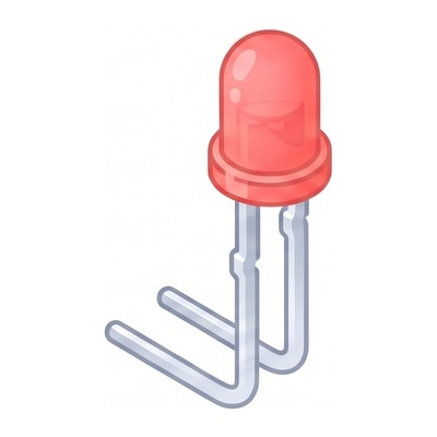
| H | 90° Bending Height (H) [Example Mode 1] | 常見 2.5 ~ 8.0 mm | [Example Mode 1: 90° Bend] Vertical height from component base to 90° bend point; fixed by tooling specification |
| L | Lead Length after Bend (L) [Example Mode 1] | 常見 3.0 ~ 15.0 mm | [Example Mode 1: 90° Bend] Trimmed horizontal lead length after 90° bend; determined by cutter tooling die |
| W | Lead Wire Diameter (W) [Example Mode 1] | Ø0.4 ~ Ø1.0 mm | [Example Mode 1: 90° Bend] Compatible lead wire diameter; tooling clearance machined per wire gauge |
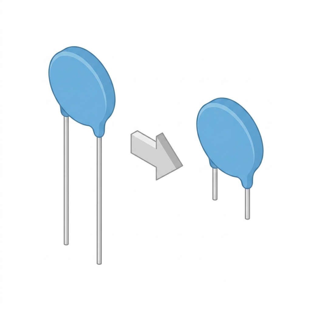
| W | Lead Wire Diameter (W) [Example Mode 2] | Ø0.4 ~ Ø1.0 mm | [Example Mode 2: Lead Spreading] Compatible lead wire diameter; custom press tooling with anti-pinching clearance |
| P | Spread Lead Pitch (P) [Example Mode 2] | 標準 5.0 / 7.5 / 10.0 mm | [Example Mode 2: Lead Spreading] Spread/reduced lead pitch for insertion into PCB mounting holes |
| H | Lead Length after Forming (H) [Example Mode 2] | 常見 3.0 ~ 8.0 mm | [Example Mode 2: Lead Spreading] Effective vertical lead length after pitch spreading for PCB through-hole insertion |
| L | Total Lead Length (L) [Example Mode 2] | 常見 10.0 ~ 25.0 mm | [Example Mode 2: Lead Spreading] Total lead length from component base to lead tips |
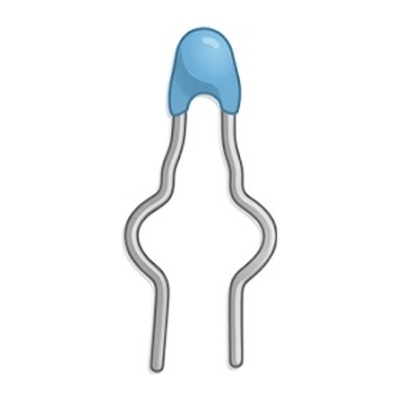
【Custom Tooling Notice】The profiles illustrated above (Mode 1: 90° Bending and Mode 2: Lead Spreading) represent common standard examples only. Ren Thang provides bespoke precision mold making services. Alternative forming geometries—such as kinks, pitch reduction, step bends, and multi-action forming—are fully supported and custom-machined per your engineering drawings and component specifications.